Battery Charger Circuit For Electric Vehicle Charger
Battery Charger Circuit For Electric Vehicle Charger. Posted by graham lambert | diy electronics | 2. In this guide from electrly, we delve into the mechanics, charging speed, and essential factors to consider when utilizing level 1 ev chargers, ensuring a seamless transition to electric vehicle ownership.
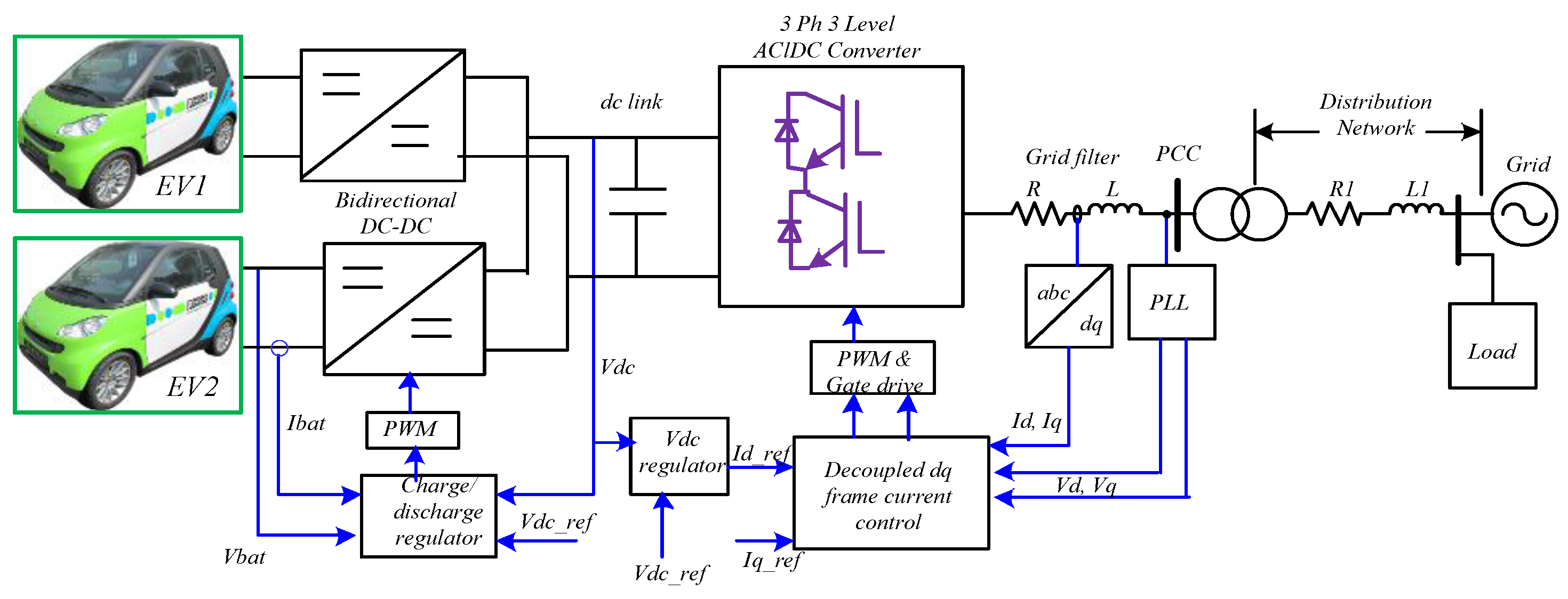
Car battery charger circuit working principle: In this paper, the impacts of evcs on utility grid are analyzed using matlab simulink model shown in fig.
Posted By Graham Lambert | Diy Electronics | 2.
In this paper, the impacts of evcs on utility grid are analyzed using matlab simulink model shown in fig.
The Charger Creates A Magnetic Field Around The Coils, Which Induces A Current In Them.
It also includes various components that regulate and control the charging process, such as voltage regulators, current limiters, and charge controllers.
Diagram Of Circuit On The Left Of The Diagram Is The Input From The Power Grid.
Images References :
 Source: guidemanualschreiner.z19.web.core.windows.net
Ev Charger Circuit Diagram, The battery's short lifetime and the long charging time are among the most critical ev issues. With the advancement of power electronics technology, electric vehicle battery charging applications have get more relevant today.
 Source: www.homemade-circuits.com
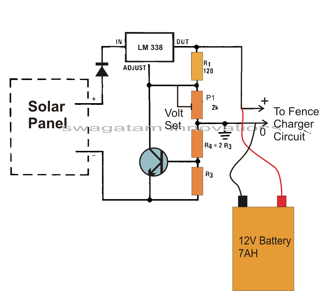
How to Make an Automatic 12 volt Battery Charger Circuit Using IC LM 338, The entire system consists of two major divisions, those are, ev charger and motor controller, which determine the arrangement of the battery, acting as load or source, and the motor that comes into action during the driving. This controls the flow of electricity into the charger and regulates the charging process.
 Source: wiringlibrichter.z19.web.core.windows.net
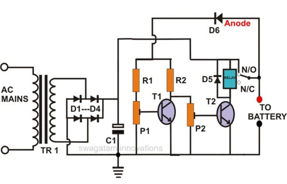
Car Battery Charger Circuit Diagram, The entire system consists of two major divisions, those are, ev charger and motor controller, which determine the arrangement of the battery, acting as load or source, and the motor that comes into action during the driving. It also includes various components that regulate and control the charging process, such as voltage regulators, current limiters, and charge controllers.
 Source: schematic-diagram.blogspot.com
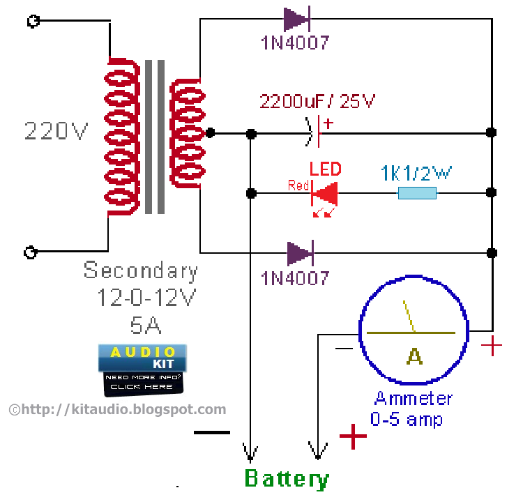
Electronic Schematic Diagrams and Circuits 12 VOLT CAR BATTERY CHARGER, Diagram of circuit on the left of the diagram is the input from the power grid. 1 which illustrates the two converters;
 Source: www.eleccircuit.com
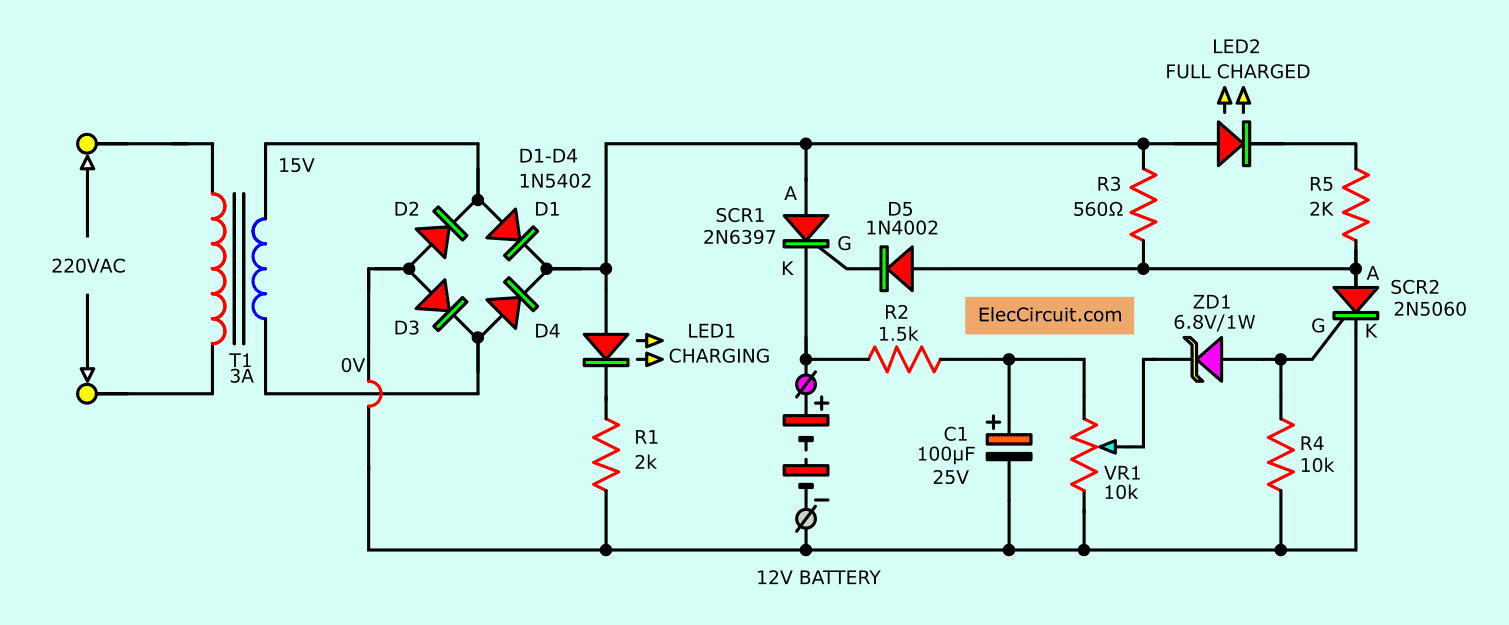
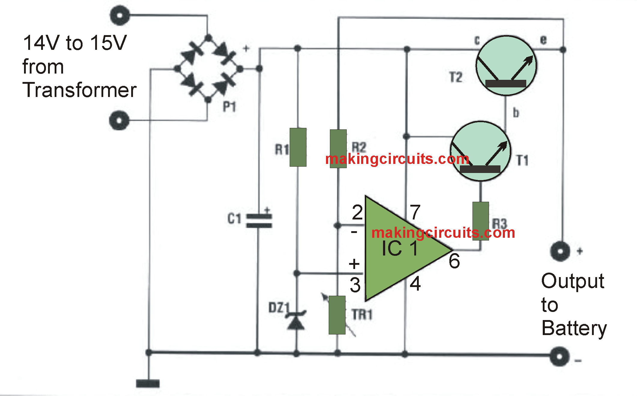
Automatic Battery Charger Circuit projects, The battery is charged from a 230v, 50hz ac mains supply. This controls the flow of electricity into the charger and regulates the charging process.
 Source: wirelibraryulrich.z13.web.core.windows.net
60 Volt Battery Charger Circuit Diagram, Posted by graham lambert | diy electronics | 2. In this modeling, the three phase source is used as utility grid and the battery.
 Source: bestchargers.eu
Overview of EV Charging Modes Bestchargers, In this tutorial, we will take a look at charging circuits for sealed lead acid (sla), nickel cadmium (nicd), nickel metal hydride (nimh), and lithium polymer (lipo) batteries. With the advancement of power electronics technology, electric vehicle battery charging applications have get more relevant today.
 Source: fixlistandreas123.z13.web.core.windows.net
Diy Car Battery Saver Diagram, The battery's short lifetime and the long charging time are among the most critical ev issues. In this modeling, the three phase source is used as utility grid and the battery.
 Source: www.youtube.com
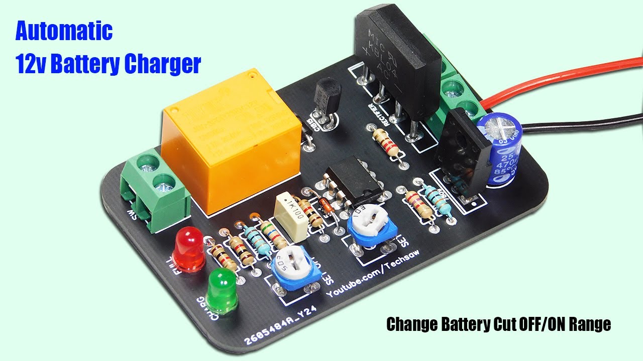
Automatic 12v Battery Charger Circuit Auto Cut OFF & ON YouTube, The challenge is to keep the temperature rise to under 5°c. The main (central) region of the diagram shows the main components within the charger itself and finally, the far right area of the diagram shows the batteries used to power the electric vehicle.
 Source: makingcircuits.com
Automatic 12V Battery Charger Circuit, Added capacitor c2 1000uf to filter and diode d1 (1n4001) across relay coil to protect q2. This training session is an introduction to the main features of battery chargers for electric vehicle applications.
The Challenge Is To Keep The Temperature Rise To Under 5°C.
In this paper, the impacts of evcs on utility grid are analyzed using matlab simulink model shown in fig.
The Alternating Current Ac Can Be Either Single Or 3 Phase Depending On The Chargers.
In this paper, the design and simulation of a smart and fast ev battery charger based on a vienna rectifier (vr) and an isolated dual active bridge (dab.